resulting weld deposits exhibit excellent tie-in and a flat
bead profile (Figure 2). Additionally, spatter and overspray
levels are the lowest in the industry, with high deposition
efficiency. The resultant weld deposits can be characterised
by a high concentration of uniformly-distributed primary
chromium carbides throughout (Figures 3 and 4).
Procedures for the reapplication of chromium
carbide cladding on a worn elbow
The following section assumes a worn elbow has been taken
out of service following inspection.
)
)
Prior to repairing the existing cladding, the elbow
should be preheated in a large oven to 600°F (316°C)
in an attempt to burn off as much of the hydrocarbon
contamination on the surface and within the cross
check cracks of the original chrome carbide overlay as
possible.
)
)
Next, the inside diameter of the pipe surface should be
cleaned and inspected for spalling prior to welding the
new chromium carbide overlay.
)
)
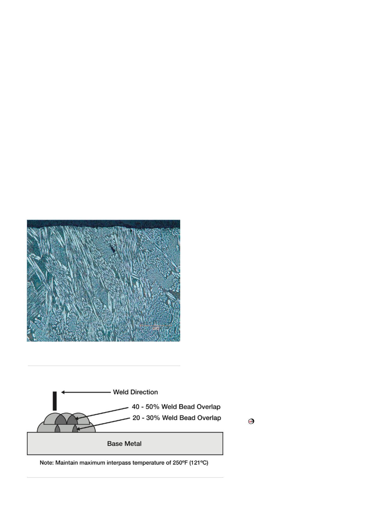
The recommended welding procedure includes the use
of stringer beads with 20 - 30% tie-in on the first layer
to establish a uniform cross check pattern (Figure 5).
This first layer is primarily used to achieve a new base
layer of chromium carbide over the top of the existing
worn overlay deposit, which may still contain a high
level of hydrocarbon contamination in the cross checks.
It is normal to see some porosity in this first layer,
although the amount can be greatly reduced by opting
to use a modified chromium carbide formulation like
Stoody PR2009 due to the high level of deoxidisers
formulated into the wire design.
)
)
A second layer of chromium carbide should then be
deposited over the first layer. If using Stoody PR2009
the degree of porosity will be substantially reduced
(Figures 1 and 2).
)
)
The weld surface of both layers should contain
cross check cracks perpendicular to the weld bead
and have hairline fractures spaced approximately
3/8 - 5/8 in. apart along a single bead. The two factors
that determine cross-check frequency and spacing
are the Interpass temperature (cooling rate) and bead
configuration. This is normally controlled by spraying
a mist of water on the outside surface of the elbow or
pipe a suitable distance from the arc on the inside of
the pipe. The cooling spray should not be directly on
the outer surface of the pipe where the welding is taking
place. If the Interpass temperature is not controlled and
becomes excessively high or the bead width too wide,
(Figure 5) the cross-check pattern will grow to greater
than 1-¼ in. apart with wide cracks running perpendicular
and longitudinal to the weld bead. Large cracks can
possibly cause catastrophic failure such as spalling.
Conclusion
With the current low price for oil placing the industry under
considerable pressure to reduce costs, one area where
savings can be made is in pipeline maintenance. In particular,
selecting the right consumable and process for cladding the
internal diameter of sections of pipeline and elbows that
have suffered abrasive wear can achieve very favourable
results. Although the optimum consumable
may not have the lowest purchase price,
the excellent deposition and weldability
characteristics in the presence of hydrocarbon
contamination, coupled with the long-term
resistance to further abrasion, can deliver a
valuable overall reduction in maintenance
costs.
NOTE: The information contained in this article
is a general overview regarding pipe and elbow ID
cladding and is for informational purposes only.
Individuals should consult with their vendor/vendor
literature for guidance in determining optimal welding
procedures for any applications.
Figure 5.
Horizontal welding – stringer bead profile.
Figure 4.
A 100X photomicrograph of the Stoody PR2009
weld deposit surface shows the concentration of uniformly
distributed chromium carbides (white) in an iron-based matrix.
124
World Pipelines
/
JUNE 2015


